
Search results
There is a page named "Bode phase plot" on Wikipedia
 frequency response, and a Bode phase plot, expressing the phase shift. As originally conceived by Hendrik Wade Bode in the 1930s, the plot is an asymptotic approximation...31 KB (4,710 words) - 10:24, 21 September 2024
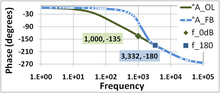 frequency where the phase lag is -135°, then the phase margin of this feedback system is -135° -(-180°) = 45°. See Bode plot#Gain margin and phase margin for more...9 KB (1,263 words) - 22:42, 11 September 2024
 analysis of stability of linear systems, inventing Bode plots, gain margin and phase margin. Bode was one of the great engineering philosophers of his...47 KB (5,209 words) - 16:57, 23 September 2024
- Therefore, both magnitude and phase graphs (Bode plots) are customarily used to examine a filter's linearity. A "linear" phase graph may contain discontinuities...7 KB (978 words) - 07:59, 22 February 2023
 Nyquist stability criterion (redirect from Nyquist-plot)by non-rational functions, such as systems with delays. In contrast to Bode plots, it can handle transfer functions with right half-plane singularities...21 KB (3,425 words) - 13:38, 26 June 2024
 {\displaystyle \omega } is the parameter along the curve. This plot may be compared to the Bode plot in which the two inter-related graphs - 20 log 10 ( |...3 KB (387 words) - 16:00, 4 October 2024
- Iso-damping (redirect from Bode's ideal transfer function)system property referring to a state where the open-loop phase Bode plot is flat—i.e., the phase derivative with respect to the frequency is zero, at a...4 KB (638 words) - 09:57, 17 April 2023
 Drain Plot. Biplot Bland–Altman plot Box plot Carpet plot Phase path of Duffing oscillator plotted as a comet plot Animated marker over a 2D plot Contour...20 KB (2,642 words) - 08:44, 28 July 2024
- Frequency response (section Measurement and plotting)common ways of plotting response measurements: Bode plots graph magnitude and phase against frequency on two rectangular plots Nyquist plots graph magnitude...11 KB (1,281 words) - 13:26, 18 June 2024
- always referred to by name. It is often discussed within the context of Bode plot methods. Minor loop feedback can be used to stabilize opamps. This example...8 KB (881 words) - 16:32, 13 October 2024
 Step response (section Phase margin)related to the phase margin of the feedback amplifier. The procedure outlined in the Bode plot article is followed. Figure 5 is the Bode gain plot for the two-pole...25 KB (3,782 words) - 20:22, 11 January 2024
 {\displaystyle A_{\text{OL}}\beta } is much greater than unity. In the Bode plot of a transimpedance amplifier with no compensation, the flat curve with...12 KB (1,825 words) - 02:38, 20 March 2024
- Analog signal processing (section Bode plots)}X(s)e^{st}\,ds} Bode plots are plots of magnitude vs. frequency and phase vs. frequency for a system. The magnitude axis is in [Decibel] (dB). The phase axis is...10 KB (1,620 words) - 03:12, 28 October 2023
- on the log of a Bode plot (log |Z| vs. log ω) exists with a slope of value –1/2. The Warburg diffusion element (ZW) is a constant phase element (CPE),...4 KB (454 words) - 14:51, 20 October 2024
- lattice, alone, is shown in Plot 2. Finally, total compensation is shown in Plot 3, when the right-hand lattice is also included. Bode devoted Chapter XII of...43 KB (6,856 words) - 01:53, 23 August 2023
 Zobel network (redirect from Bode network)in a Bode network, just as with a Zobel network, but the high pass section shown for correcting high-end frequencies is the most common. A Bode network...34 KB (5,071 words) - 01:34, 22 February 2024
 Root locus analysis (redirect from Root locus plot)determine its behavior. Phase margin Routh–Hurwitz stability criterion Nyquist stability criterion Gain and phase margin Bode plot "1990". McKelvey School...20 KB (2,859 words) - 04:52, 31 July 2024
- diagram Greninger chart Phase diagram Wavenumber-frequency diagram Bode plot Nyquist plot Dalitz plot Feynman diagram Carnot Plot Flowchart Workflow Gantt...4 KB (331 words) - 07:28, 8 February 2024
- first-order low-pass. See Pole–zero plot and RC circuit. A second-order filter attenuates high frequencies more steeply. The Bode plot for this type of filter resembles...31 KB (4,640 words) - 09:43, 13 July 2024
- using the Nyquist plot. Another method used in control loop theory uses Bode plots of gain and phase vs. frequency. Using Bode plots, a design engineer...7 KB (943 words) - 07:45, 3 June 2024


- importance are Appell, J. W. ‘Werther und seine Zeit’ (Oldenburg 1855); Bode, W., ‘Goethes Aesthetik’ (Berlin 1901); Boucke, E. A., ‘Goethe's Weltanschauung’
- Fox and Deidre McPhillips in "Covid-19 numbers seem stuck. That doesn't bode well for winter, experts say", CNN, (November 13, 2021) Saying the surge
- A Bode Plot is a useful tool that shows the gain and phase response of a given LTI system for different frequencies. Bode Plots are generally used with