Front-engine, front-wheel-drive layout
This article needs additional citations for verification. (November 2011) |
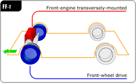
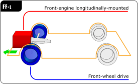
In automotive design, a front-engine, front-wheel-drive (FWD) layout, or FF layout, places both the internal combustion engine and driven roadwheels at the front of the vehicle.
Usage implications
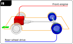
Historically, this designation was used regardless of whether the entire engine was behind the front axle line. In recent times, the manufacturers of some cars have added to the designation with the term front-mid which describes a car in which the engine is in front of the passenger compartment but behind the front axle. The engine positions of most pre–World-War-II cars are front-mid or on the front axle.
This layout is the most traditional form and remains a popular, practical design. The engine, which takes up a great deal of space, is packaged in a location passengers and luggage typically would not use. The main deficit is weight distribution—the heaviest component is at one end of the vehicle. Car handling is not ideal, but usually predictable.
In contrast with the front-engine, rear-wheel-drive layout (RWD), the FWD layout eliminates the need for a central tunnel or a higher chassis clearance to accommodate a driveshaft providing power to the rear wheels. Like the rear-engine, rear-wheel-drive layout (RR) and rear mid-engine, rear-wheel-drive layout (RMR) layouts, it places the engine over the drive wheels, improving traction in many applications. As the steered wheels are also the driven wheels, FWD cars are generally considered superior to RWD cars in conditions in which there is low traction such as snow, mud, gravel or wet tarmac. When hill climbing in low-traction conditions RR is considered the best two-wheel-drive layout, primarily due to the shift of weight to the rear wheels when climbing. The cornering ability of an FWD vehicle is generally better, because the engine is placed over the steered wheels.[1] However, as the driven wheels have the additional demands of steering, if a vehicle accelerates quickly, less grip is available for cornering, which can result in understeer.[2] High-performance vehicles rarely use the FWD layout because weight is transferred to the rear wheels under acceleration, while unloading the front wheels and sharply reducing their grip, effectively capping the amount of power which could realistically be utilized; in addition, the high power of high-performance cars can result in torque steer. Electronic traction control can avoid wheel-spin but largely negates the benefit of extra power.[3] This was a reason for the adoption of the all-wheel-drive quattro system in the high performance Jensen FF and Audi Quattro road cars.
Historical arrangements
Early cars using the FWD layout include the 1925 Alvis, 1929 Cord L-29, 1931 DKW F1, the 1948 Citroën 2CV, 1949 Saab 92, the 1957 Trabant P50, and the 1959 Mini. In the 1980s, the traction and packaging advantages of this layout caused many compact and mid-sized vehicle makers to adopt it in the US. Most European and Japanese manufacturers switched to front wheel drive for the majority of their cars in the 1960s and 1970s, the last to change being VW, Ford of Europe, and General Motors (Vauxhall - UK and Opel - Germany). Toyota was the last Japanese company to switch in the early 1980s. BMW, focused on luxury vehicles, however retained the rear-wheel-drive layout in even their smaller cars,[4] though their MINI marque are FWD.
There are four different arrangements for this basic layout, depending on the location of the engine, which is the heaviest component of the drivetrain.
Mid-engine / Front-wheel drive
The earliest front wheel drive cars were mid-engine, front-wheel-drive layout (MF). The engine was mounted longitudinally (fore-and-aft, or north–south) behind the wheels, with the transmission ahead of the engine and differential at the very front of the car. With the engine so far back, the weight distribution of such cars as the Cord L-29 was not ideal; the driven wheels did not carry a large enough proportion of weight for good traction and handling. The 1934 Citroën Traction Avant solved the weight distribution issue by placing the transmission at the front of the car with the differential between it and the engine. Combined with the car's low slung unibody design, this resulted in handling which was remarkable for the era. Renault is the most recent user of this format - having used it on the Renault 4, and the first generation Renault 5, but it has since fallen out of favor since it encroaches into the interior space.
Longitudinally mounted front-engine and front-wheel drive
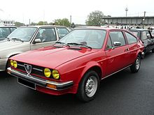
The 1946 Panhard Dyna X, designed by Jean-Albert Grégoire, had the engine longitudinally in front of the front wheels, with the transmission behind the engine and the differential at the rear of the assembly. This arrangement, used by Panhard until 1967, potentially had a weight distribution problem analogous to that of the Cord L29 mentioned above. However, the Panhard's air-cooled flat twin engine was very light, and mounted low down with a low centre of gravity reducing the effect. The air-cooled flat twin engine of the Citroën 2CV was also mounted very low, in front of the front wheels, with the transmission behind the axle line and the differential between the two. This became quite popular; cars using this layout included the German Ford Taunus 12M and the Lancia Flavia and Fulvia. This is the standard configuration of Audi and Subaru front-wheel-drive vehicles. In 1979, Toyota introduced and launched their first front-wheel-drive car, the Tercel, and it had its engine longitudinally mounted, unlike most other front-wheel-drive cars on the market at that time. This arrangement continued also on the second-generation Tercel, until 1987, the third generation received a new, transversely mounted engine. Other front-wheel-drive Toyota models, such as Camry, and Corolla, had transversely mounted engines from the beginning on.
The 1966 Oldsmobile Toronado (along with its sister model the Cadillac Eldorado) used a novel arrangement which had the engine and transmission in a 'side-by-side' arrangement with power being transmitted between the two via a heavy-duty chain, and a specially designed intermediate driveshaft that passed under the engine sump. This family has the distinction of being the highest engine capacity (8.2 L) front-wheel-drive vehicles ever built. The Saab 99 and “classic” Saab 900 also used a similar arrangement. The Eagle Premier used a similar powertrain arrangement found in the Renault 21 and 25 – later becoming the basis for the Chrysler LH sedans produced until the 2004 model year.
Today, Audi is the most prominent user of this mechanical layout, having used it since the 1950s in its predecessor companies DKW and Auto Union, and it can be found in its larger models from the A4 upward. The latest evolution of the format in Audi's MLB platform attempts to address the long-standing drawback of uneven weight distribution. This is done by packaging the differential in front of the clutch, allowing the axle line to be further forward in relation to the rear face of the engine block.
Front-engine transversely mounted / Front-wheel drive
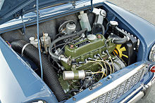
The first popular transverse engined FWD cars were the DKW 'Front' made from 1931, which had a twin cylinder two-stroke engine. Saab copied this design on their first car, the 1949 Saab 92. The Trabant in 1957 was also one of the only cars to have a transverse mounted engine, being a sort of DKW successor. This was a novelty, especially for a car being made in a communist country.
Issigonis's Mini of 1959 and related cars such as the Maxi, Austin 1100/1300 and Allegro had the four-cylinder inline water-cooled engine transversely mounted. The transmission was located in the sump below the crankshaft, with power transmitted by transfer gears. Other models that used the "transmission-in-sump" layout included the Datsun 100A (Cherry) and various applications of the PSA-Renault X-Type engine such as the Peugeot 104 and Renault 14. The 1955 Suzuki Suzulight also introduced a front engine with a transversely installed two-stroke twin-cylinder engine (using DKW technology) in a city car/kei car application, based on the German Lloyd LP400.
Dante Giacosa's Autobianchi Primula of 1964, Fiat 128 and Fiat 127, put the transmission on one side of the transversely mounted engine, and doubled back the drivetrain to put the differential just behind the transmission, but offset to one side. Hence the driveshafts to the wheels are longer on one side than the other. This located the weight just a bit in front of the wheels. It is this system which dominates worldwide at present.
Front-wheel-drive vehicles tend to suffer from torque steer under heavy acceleration.[5] This is caused by differing drive shaft lengths which in turn results in different incident angles at the joints of the driveshaft. The farther these joints are articulate, the less effective they are at delivering torque to the wheels.
Front-wheel drive design characteristics
-
Longitudinally front-mounted engine, front-wheel drive (FF longitudinal layout): The Auto Union 1000, (today Audi) longitudinal layout superseded the DKW F89 front transverse engines in the 1950s.
-
Transverse front-mounted engine, front-wheel drive (FF transverse layout): Fiat 128, followed the footsteps of the Autobianchi Primula.
Front-wheel drive shafts
In front wheel drive vehicles, the drive shafts transfer the drive directly from the differential to the front wheels. A short inner stub shaft is splined to the differential side gear and an outer stub shaft is splined to the front wheel hub. Each stub shaft has a yoke, or housing, to accommodate a universal joint, at each end of a connecting intermediate shaft.
Universal joints let the shaft keep rotating while allowing for changes due to suspension movement, such as shaft length and horizontal angle, and shaft angle as the steering turns. Constant-velocity universal joints are normally used to transfer power smoothly between the components. The inner universal can be a plunge or tripod type joint. The tripod is splined to the intermediate shaft and held by a circlip. A ball, supported on needle roller bearings, is fitted to each post of the tripod, and these slide in a trunion inside the yoke. This caters for changes in shaft length and horizontal angle. The drive is transferred through the trunion and balls to rotate the shaft.
The outer universal joint allows greater angular changes but not changes in shaft length. It is normally a ball and cage type with an inner race splined to the intermediate shaft. An outer race is formed in the yoke. The cage retains the balls in location in grooves in both races. The balls transfer the drive from the shaft to the hub and allow for changes in horizontal angle and for a wide steering angle to be achieved. A flexible rubber boot fitted to each joint retains grease and keeps out dirt and moisture.
Where the differential is not located in the center line of the vehicle, an intermediate shaft can be fitted to maintain equal length drive shafts on each side. This keeps drive shaft angles equal on both sides and helps prevent steering irregularities and vibration. The outer end of the intermediate shaft is supported by a bearing secured to the transaxle case and a universal joint assists with alignment. In some cases a longer drive shaft is used on one side. A rubber dynamic damper may be fitted to absorb vibrations.
See also
References
- ^ Hillier, Victor; Peter Coombes (2004). Fundamentals of motor vehicle technology. Nelson Thornes. p. 9. ISBN 978-0-7487-8082-2.
- ^ "Engine & Driveline Layouts". Drivingfast.net. Archived from the original on 27 September 2016. Retrieved 6 January 2010.
- ^ www.motortrend.com Archived 2011-07-18 at the Wayback Machine Road Test: Rear Drive vs. Front Drive vs. All-Wheel Driv
- ^ "BMW Technology Guide: Rear wheel drive". Retrieved 1 September 2016.
- ^ "What the heck is torque steer?".
Further reading
- Sedgwick, Michael Cars of the 50s and 60s. Gothenburg, Sweden: A B Nordbok, 1983. (Includes pictures of the engine layouts of the Traction Avant and other designs.)


